Item Description
Not all items can be in stock at all
times.
Due to minimum order requirements and shipping charges we
"bunch" up re-orders to save you money.
(We reserve the right to correct errors and change
prices without prior notice.)
|
Pricing
| Order link |
|
Note:
Not all of the items below may be in stock or available but
the information is provided for reference purposes.
|
Please copy & paste the entire description TEXT (no pictures
please)from the
item you are ordering into your e-mail.
It will save time and reduce possible confusion in determining
what you
really are ordering.
With the quantity of lines we carry it's not possible to memorize
all of them.
|
Be
sure you review our terms pages before placing your order:
First: Terms
Page One Finally: Terms Page Three
If you place an order, you have agreed to our terms. |
Please
remember to give your first and last name and the city and
state where you live in all your e-mails.
Non-USA
customers please include the country. |
|
Click here to see the new Air Horns
|
|
Item Description
|
Pricing
| Order link |
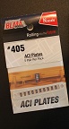
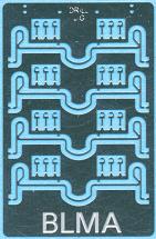
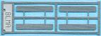
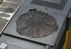
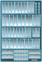
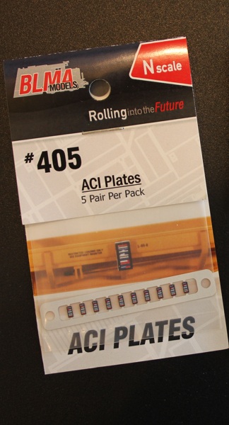
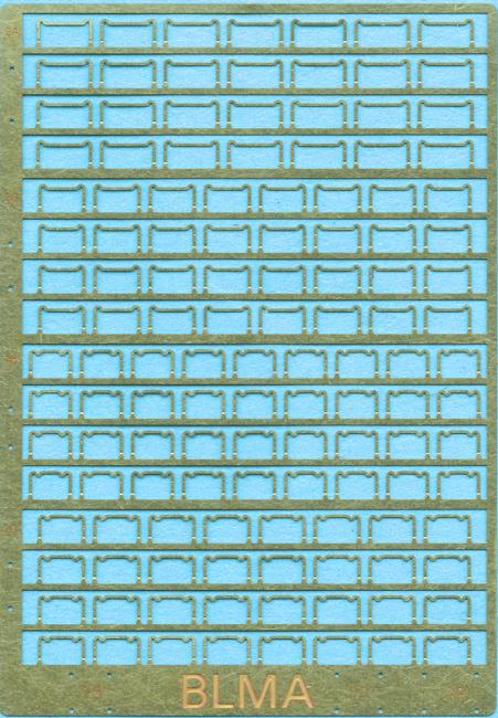
| Part #: BLMA-405 ACI Plates (5 pair) |
Model Description:
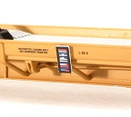
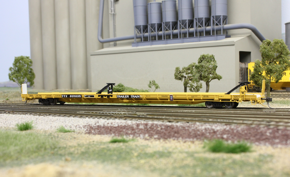
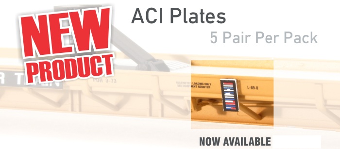
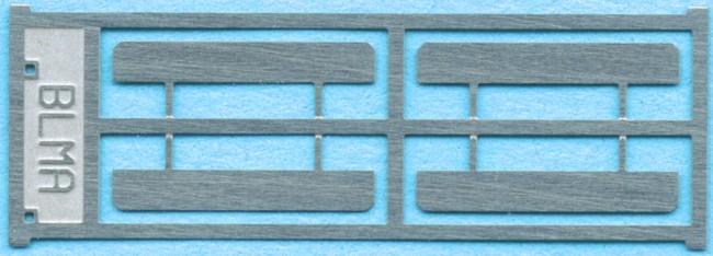
For 1970’s+ era rolling stock. These ACI plates are the FIRST produced that you simply glue to a car side. This package contains 10 ACI plates - enough for five pieces of rolling stock!
Prototype History:
Developed in the late 1960's for rolling stock identification, the ACI plates became a common sight throughout the 1970's and beyond. Ultimately, the program failed due to dirty, unreadable railcars and more sophisticated reading systems (the modern AEI tag).
Installation Instructions
Simply cut the etched-metal ACI plates from the fret, glue to your model and enjoy. Simple as pie! Wig-Wag Note: If you ever met George's Grandmother she could get 14-18 pieces out of an 8" pie. |
| Click on Photo for Large View |
|
 |

|
 |
|
.Click
Here For
Pricing |

Click to place a
Secure Order On-Line |
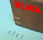
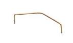
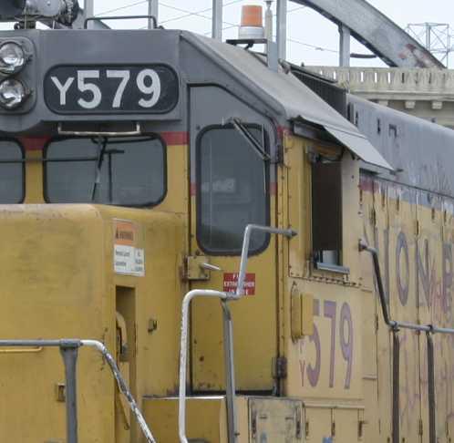
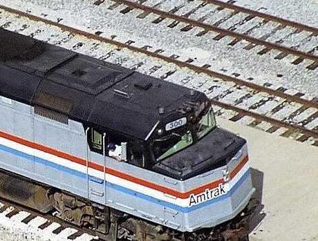
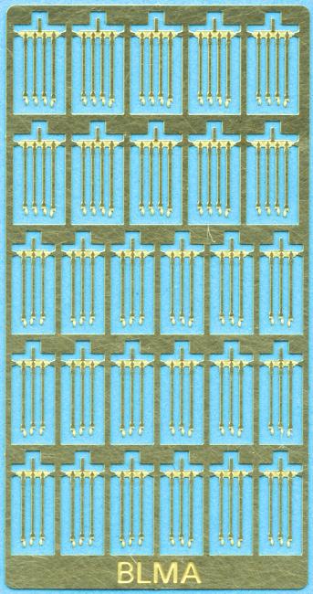
| Part #: BLMA-13 Modern EMD
Locomotive Cut Levers-1 pair |
This style of cut levers is common on all EMD diesel locomotives produced after the early-mid 1970's. Each set includes one pair of chemically-etched, Modern EMD Cut Levers and associated mounting pins.
This product is also available in a bulk pack - BLMA #62 |
Installation Instructions
1. Remove cut levers from etching frame with a sharp hobby knife blade.
2. Bend the middle ‘U’ section perpendicular to both outside handles of the cut lever (see prototype photo to the right). To make this bend, we suggest grasping one side of the ‘U’ with toothless pliers and grasping one side of the cut lever with another pair of pliers. With little force, rotate one hand 90 degrees to make the ‘U’ perpendicular to the outside of the cut lever.
3. Complete step two for both sides of the cut lever.
4. Next, notice that the ends of the cut levers have small nubs that bend outwards at the very bottom of the handles. For a more realistic look, bend these small nubs 90 degrees so they are facing the opposite direction of the ‘U’ (which would be toward the locomotive, not away from it).
5. Remove the mounting pins supplied with the cut levers and use the holes in the etched fret as a drilling template. Simply tape the drilling template to the front of the locomotive at the proper height (consult prototype photos) and drill through the holes using a #80 drill.
6. Loop four of the mounting pins onto the cut lever, add a dab of glue on the holes drilled in step six and mount the cut lever to the model.
7. Paint as appropriate. |
For More Model Images Click Here |
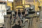
Prototype Image
|
|
.Click
Here For
Pricing |
Click to place a
Secure Order On-Line |
| Part #: BLMA- 14 Modern GE Locomotive Cut Levers - (2 pair) |
| Chemically-etched in stainless steel for durability and scale fidelity, our General Electric-type cut levers follow a similar design to our EMD Modern Cut Levers, requiring minor bending. Included in each set are four cut levers, mounting pins, and a drill template. |
Installation Instructions
1. Remove cut levers from etching frame with a sharp hobby knife blade.
2. Bend the middle ‘U’ section perpendicular to both outside handles of the cut lever (see prototype photo to the right). To make this bend, we suggest grasping one side of the ‘U’ with toothless pliers and grasping one side of the cut lever with another pair of pliers. With little force, rotate one hand 90 degrees to make the ‘U’ perpendicular to the outside of the cut lever.
3. Complete step two for both sides of the cut lever.
4. Next, notice that the ends of the cut levers have small nubs that bend outwards at the very bottom of the handles. For a more realistic look, bend these small nubs 90 degrees so they are facing the opposite direction of the ‘U’ (which would be toward the locomotive, not away from it).
5. Remove the mounting pins supplied with the cut levers and use the holes in the etched fret as a drilling template. Simply tape the drilling template to the front of the locomotive at the proper height (consult prototype photos) and drill through the holes using a #80 drill.
7. Loop four of the mounting pins onto the cut lever, add a dab of glue on the holes drilled in step six and mount the cut lever to the model.
7. Paint as appropriate. |
Model Image
|
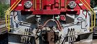
Prototype Image
|
|
.Click
Here For
Pricing |
Click to place a
Secure Order On-Line |
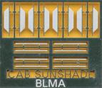
| Part #: BLMA-16 Modern EMD
Cab Sunshades - 4ea |
| EMD began using a longer style cab sunshade with their SD60M model and continued using this style on some roads through the SD90 series. |
Installation Instructions
1. Remove cab sunshades from etched frame with a sharp hobby knife or by gently rocking them back and forth.
2. Use the drilling holes etched into the frame to guide your hole drilling (use a #80 drill bit).
3. Mount with super glue. |
|
|
.Click
Here For
Pricing |
Click to place a
Secure Order On-Line |
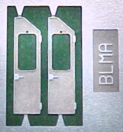
| Part #: BLMA-17
Spartan Style Cab Doors - 2ea |
| Prop your locomotive cab door open! We've all seen it...A train rumbles past with the cab door open. Or, a yard job shuffles cars around with 'added visibility' through an open front or back cab door. Or, the local power is idling with doors open for maintenance access. Whatever the case may be, open cab doors are an interesting modeling idea that dramatically enhances a locomotives believability. Used on dozens of GP and SD diesels, our Spartan Cab Doors are a perfect fit on nearly all non-wide cab EMD diesel locomotives. These doors will come in handy during kit-bashes or a locomotive shop scene. |
Installation Instructions
1. Remove door from etched frame with a sharp hobby knife.
2. If you are going to "prop" the door open on one of your models, we suggest painting it at this time.
3. To remove a molded - on door from a plastic shell, we suggest drilling a series of small holes, connecting them with a sharp blade, then cleaning out the excess with a combination of blades and files.
4. Notice that there is a hole directly above the window to mount a windshield wiper (BLMA #96).
5. We suggest using clear styrene for the window though Microscale's Krystal Klear would work as well. |
|
|
|
.Click
Here For
Pricing |
Click to place a
Secure Order On-Line |
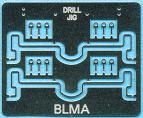
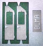
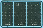
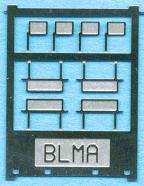
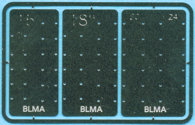
| Part #: BLMA-57 Grab
Iron Drill Templates - (4 sizes) |
Our Drill Templates have the following features:
- Etched Metal: Extremely durable and will last forever.
- Extremely Accurate: The hole spacing is literally exact.
- Four Sizes: Included are 15", 18", 20" & 24" grab iron templates for nearly all models.
Struggling to install grab irons on your model? This set of drill jigs will considerably ease the process. |
Installation Instructions
Simply locate the proper drill jig for the grab iron size you'll be working with, remove it from the etched fret and tape it to the model exactly where you need it.
Note that the "BLMA" etched into the bottom of the jigs references the bottom and if you're drilling grab irons on the rear hood of an EMD or GE locomotive, the jig should be flush with the bottom of the shell (but please check before you drill!). |
|
|
.Click
Here For
Pricing |
Click to place a
Secure Order On-Line |
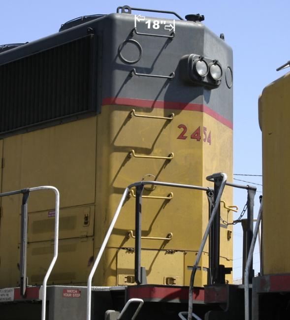
| Part #: BLMA-58 18" Straight Grab Irons (.007" wire) - 20 ea |
| These highly accurate grab irons are bent into shape by machine to ensure accuracy and sharp bends. The wire is stainless steel with a diameter of roughly .007" which makes our grab irons extremely close to scale. |
Installation Instructions
1. Remove molded - on grab irons with a sharp hobby knife blade (#11) or the broader chisel blade.
2. Before sanding the shell surface smooth (if it already isn't), use the molded on grab iron markings as the template to drill your new holes or use our etched-metal drill template (BLMA #57). Drill the holes for the grab irons using a #80 or smaller drill bit.
3. Once your holes are drilled, you can sand down the surface of the shell to totally remove the old molded on grab irons (though sometimes you can get things flush with just your blade).
4. We suggest using toothless pliers to grasp the grab iron while installing.
5. By this point, all of your holes should be drilled. Without using glue, insert grab irons into the holes. This step will give you a good indication of how things are lining up before they are glued in place.
6. After the grab irons are installed without glue and look straight and uniform, remove the grab irons one by one with toothless pliers, dab the ends in super glue, then reinsert them leaving the grab iron away (not flush) with the shell. Once you have one grab iron glued in place, use it as a guide to how far out you will place the rest of the grab irons - .023" is perfect.
7. Once all of the grab irons are in place you might notice that a few are not exactly parallel. This can be fixed with a gentle hand and toothless pliers. Without grasping the wire to hard, gently bend the iron into the correct position
8. If you would like to paint the grab irons be sure you to use thin paint |
|
|
.Click
Here For
Pricing |
Click to place a
Secure Order On-Line |
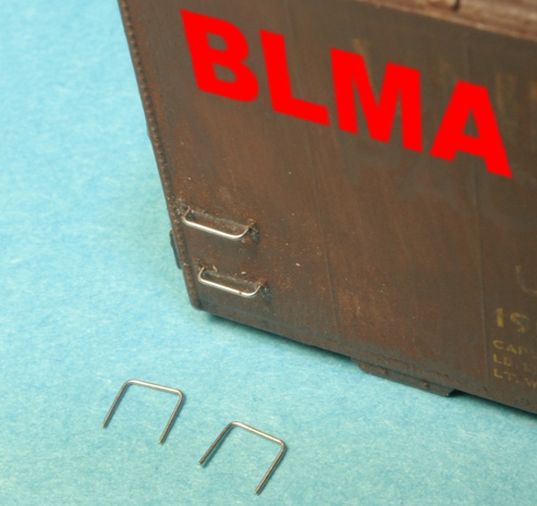
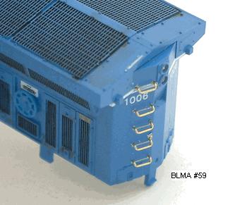
| Part #: BLMA-59 15" Grab
Irons with Drop (.009" wire) - 20 ea |
| These highly accurate grab irons are bent into shape by machine to ensure accuracy and sharp bends. The wire is brass with a diameter of roughly .009" which makes it very easy to work with. |
Installation Instructions
1. Remove molded - on grab irons with a sharp hobby knife blade (#11) or the broader chisel blade.
2. Before sanding the shell surface smooth (if it already isn't), use the molded on grab iron markings as the template to drill your new holes or use our etched-metal drill template (BLMA #57). Drill the holes for the grab irons using a #80 or smaller drill bit.
3. Once your holes are drilled, you can sand down the surface of the shell to totally remove the old molded on grab irons (though sometimes you can get things flush with just your blade).
4. We suggest using toothless pliers to grasp the grab iron while installing.
5. By this point, all of your holes should be drilled. Without using glue, insert grab irons into the holes. This step will give you a good indication of how things are lining up before they are glued in place.
6. After the grab irons are installed without glue and look straight and uniform, remove the grab irons one by one with toothless pliers, dab the ends in super glue, then reinsert them leaving the grab iron away (not flush) with the shell. Once you have one grab iron glued in place, use it as a guide to how far out you will place the rest of the grab irons - .023" is perfect.
7. Once all of the grab irons are in place you might notice that a few are not exactly parallel. This can be fixed with a gentle hand and toothless pliers. Without grasping the wire to hard, gently bend the iron into the correct position
8. If you would like to paint the grab irons be sure you to use thin paint. |

|
|
.Click
Here For
Pricing |
Click to place a
Secure Order On-Line |
| Part
#: BLMA-60 18" Drop
Grab Irons (.007" wire) - 20 ea |
| These highly accurate grab irons are bent into shape by machine to ensure accuracy and sharp bends. The wire is stainless steel with a diameter of roughly .007" which makes them very close to scale. |
Installation Instructions
1. Remove molded - on grab irons with a sharp hobby knife blade (#11) or the broader chisel blade.
2. Before sanding the shell surface smooth (if it already isn't), use the molded on grab iron markings as the template to drill your new holes or use our etched-metal drill template (BLMA #57). Drill the holes for the grab irons using a #80 or smaller drill bit.
3. Once your holes are drilled, you can sand down the surface of the shell to totally remove the old molded on grab irons (though sometimes you can get things flush with just your blade).
4. We suggest using toothless pliers to grasp the grab iron while installing.
5. By this point, all of your holes should be drilled. Without using glue, insert grab irons into the holes. This step will give you a good indication of how things are lining up before they are glued in place.
6. After the grab irons are installed without glue and look straight and uniform, remove the grab irons one by one with toothless pliers, dab the ends in super glue, then reinsert them leaving the grab iron away (not flush) with the shell. Once you have one grab iron glued in place, use it as a guide to how far out you will place the rest of the grab irons - .023" is perfect.
7. Once all of the grab irons are in place you might notice that a few are not exactly parallel. This can be fixed with a gentle hand and toothless pliers. Without grasping the wire to hard, gently bend the iron into the correct position
8. If you would like to paint the grab irons be sure you to use thin paint. |
Model Image
|
Prototype Image
|
|
.Click
Here For
Pricing |
Click to place a
Secure Order On-Line |
Part
#: BLMA-61 18" Drop
Grab Irons BULK PACK - 60 ea
Refer to data above |
.Click
Here For
Pricing |
Click to place a
Secure Order On-Line |
Part #: BLMA-62 Bulk Pack of BLMA #13 - 10 ea
Refer to Part # 13 |
.Click
Here For
Pricing |
Click to place a
Secure Order On-Line |
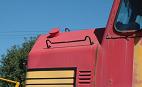
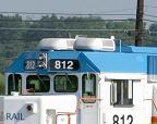
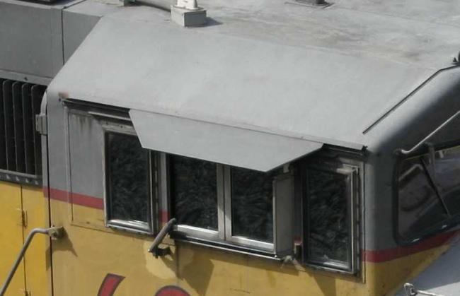
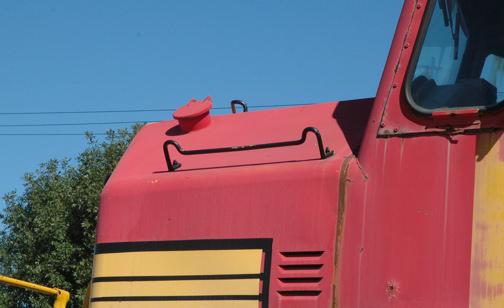
| Part #: BLMA-64 Locomotive Wind Deflectors - (8
pair) |
Found on a good number of diesel locomotives, Wind Deflectors were mounted onto locomotive cab sides to do what their name says - deflect wind. Similar to a rear view mirror, wind deflectors feature a see-through glass center that doesn't hinder sight; they deflect wind for the train crew.
Our extremely accurate wind deflectors are the perfect addition to your diesel models. |
|
|
.Click
Here For
Pricing |
Click to place a
Secure Order On-Line |
| Part
#: BLMA-65 Modern
Rear View Mirrors - (Reg. & Small) (8) |
| This set includes two styles of commonly used diesel locomotive Rear View Mirrors. These mirrors are perfect for nearly any style of diesel locomotives. Four of each style are included per etching |
Installation Instructions
1. Remove the rear view mirrors from the metal frame with a sharp knife or by gently bending them back and forth.
2. Using the drilling template provided on the etched fret, drill the proper holes on your cab using a #80 drill bit. Consult reference photos for proper location and mirror type.
3. Test fit the mirror in the holes you have drilled to ensure everything lines up correctly.
4. Remove the mirror from the holes with tweezers, dip the mounting pegs in glue and reinsert (the small rear view mirror only needs one hole to mount it). |
|
|
.Click
Here For
Pricing |
Click to place a
Secure Order On-Line |
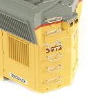
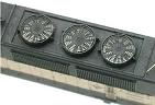
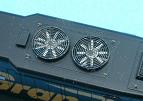
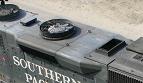
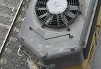
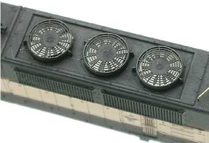
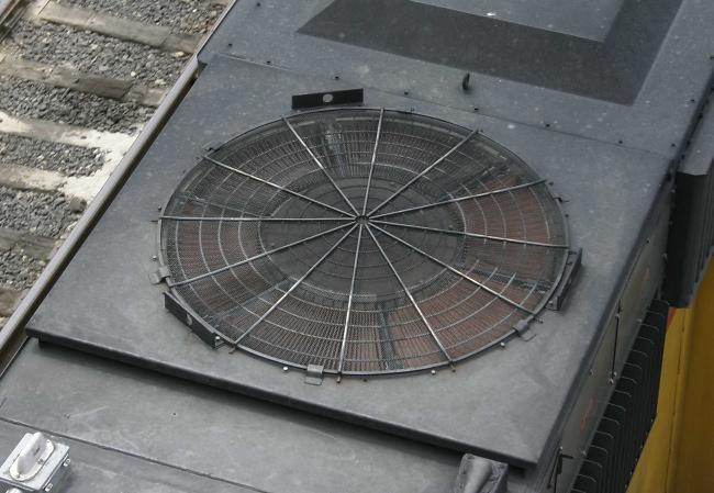
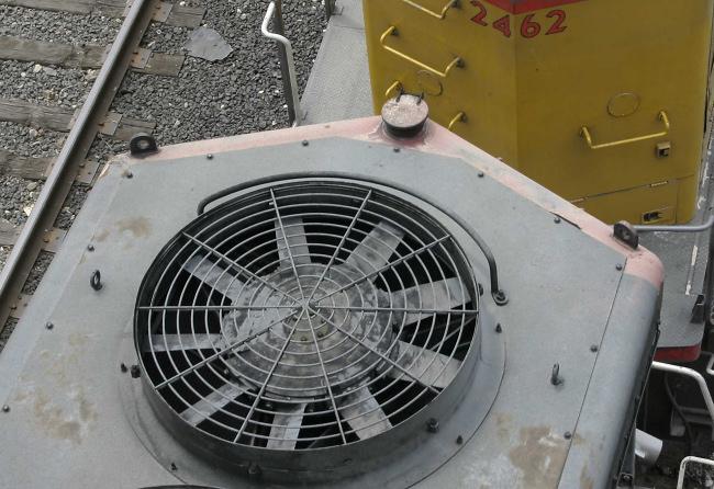
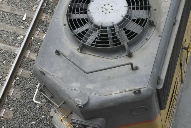
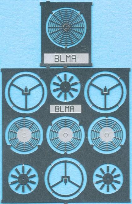
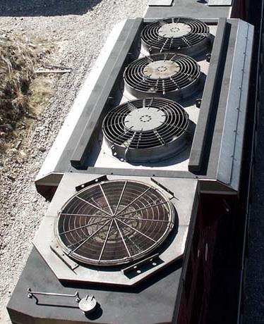
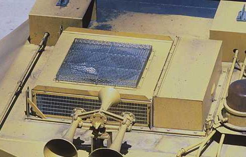
| Part #: BLMA-66 Modern EMD Fan Package - (3) - 53" & (1)60" |
| This fan set is designed to retrofit/upgrade the fans on later generation EMD's which includes all models in the SD70, 80 and 90 range. Each set includes one 60" Dynamic Brake Grill and three sets of 53" Radiator Fan Grills with Blades. |
Installation Instructions
1. Drill out existing fans, leaving only the round fan housing in place (notice we do not include a new fan housing, ONLY the top grill).
2. File or sand the top of the fan housing down no more then .005” to compensate for the new fan grills’ thickness
3. Putting the shell to the side, remove all pieces from the etched metal frame using a sharp hobby knife. The large round “peace sign” looking part is the first you will work with (note that the single 60" dynamic brake grill does not include any fan blades or underside detail).
4. In the middle of this part you will notice a small tab with a half etched line going through the bottom of it. Bend this tab straight up and down so it is perpendicular to the rest of the etching.
5. Next, mount your fan blade etching directly on top of the tab that you bent up in step four. The fan blade etching should be suspended above the lower piece (peace sign looking part). Secure with a dab of super glue. For added realism, turn each fan blade a few degrees (like on a ceiling fan).
6. Next, spread glue on the underside of one fan housing (meaning that you will spread glue around the opening of the fan on the INSIDE of the shell). While looking down on the model, bring your blade/bottom piece assembly up from inside the shell so the bottom piece comes in contact with the glue (spread earlier in this step). At this point, make sure that the middle of your fan blade etching is in the middle of the fan housing (it is easy to be off by a bit and this is the last chance to slightly move the assembly).
7. Once all of the fan blade assemblies are in place you can mount the top fan grill. We suggest spreading a thin layer of CA around the top of the fan housing and then placing the fan grill on top with tweezers.
8. You can either paint the top fan grills the same color as the top of the locomotive hood or leave them natural. |
For More Model Images Click Here |
For More Prototype Images Click Here |
|
.Click
Here For
Pricing |
Click to place a
Secure Order On-Line |
Part #: BLMA-67 Drop Grab Irons- Bulk Pack (60) of Part #: 59
Refer to Part #59 for installation instructions. |
.Click
Here For
Pricing |
Click to place a
Secure Order On-Line |
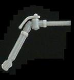
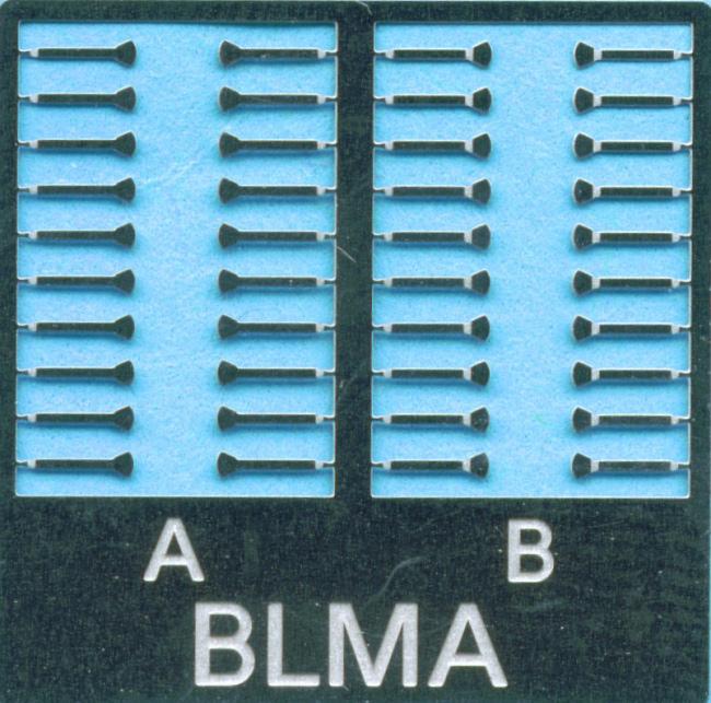
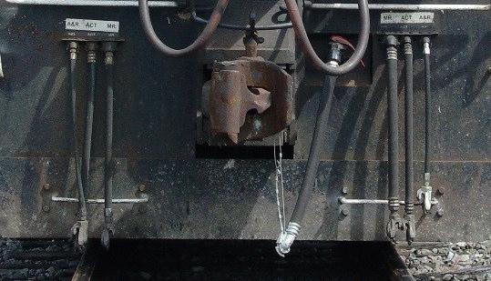
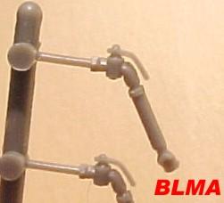
| Part #: BLMA-69 Trainline
Air Hoses (injection molded)
24 ea |
| These injection molded Trainline Air Hoses are great for all locomotives, freight cars and passenger cars. Trainline Air Hoses are found on both ends of ALL railroad rolling stock (this includes any locomotives, freight cars and passenger cars). The purpose of the Trainline Air Hose is to carry and distribute air to every car in a train for braking purposes (trains of course use an air brake system). |
Installation Instructions
1. Remove the moldings from spur with a sharp hobby knife.
2. The mount on these air hoses is .016", so a drill bit around that diameter should work fine.
3. Drill a single hole in the proper place (view prototype photos) and mount in the hole with glue.
4. We suggest painting the angle cock (top) and hose coupler silver (bottom) and the actual "hose" part a flat black (to simulate rubber). |
For More Model Images Click Here
|
For More Prototype Images Click Here
For More Prototype Images Click Here |
|
.Click
Here For
Pricing |
Click to place a
Secure Order On-Line |
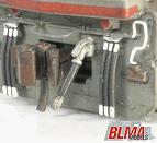
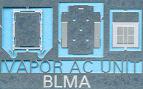
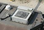
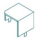
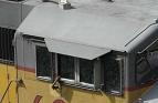
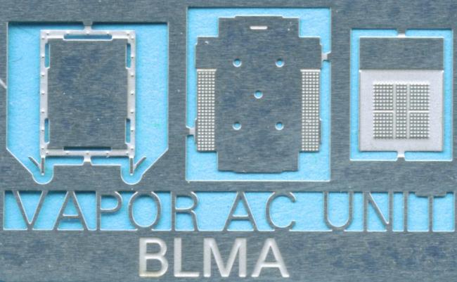
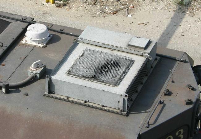
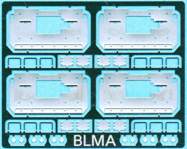
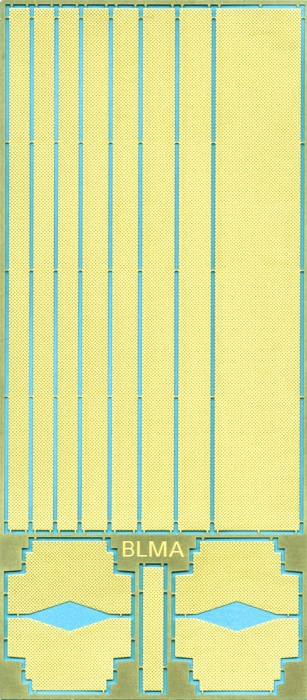
| Part #: BLMA-70 Cab Air Conditioner Kit - Vapor Style |
| Our N Scale Air Conditioners are made from fine-scale photo-etched metal allowing us to include every detail possible, even down to the correct number of rivets! |
Installation Instructions
1. Remove the three pieces of the air conditioner from the etched frame using a sharp hobby knife.
2. Notice that the center piece (with five holes in it) will fold into a box, utilizing the fold lines on it's underside. Using the method of your choice, fold the sides of this part perpendicular to the center to create a bottomless box.
3. Using a small amount of glue, mount your box from step two onto the bottom plate (rectangle surrounded by rivet detail).
4. To complete, simply glue the top etching (with grill detail) in place, mount, and paint to the desired color (consult reference photos where needed). |
For More Model Images Click Here |
For More Prototype Images Click Here |
|
.Click
Here For
Pricing |
Click to place a
Secure Order On-Line |
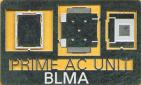
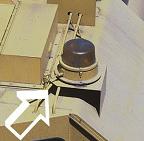
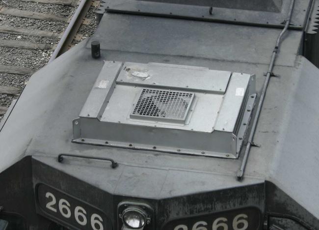
| Part #: BLMA-71 Air Conditioner
- Prime 1 ea |
| Our N Scale Air Conditioners are made from fine-scale photo-etched metal allowing us to include every detail possible, even down to the correct number of rivets! |
Installation Instructions
1. Remove the three pieces of the air conditioner from the etched frame using a sharp hobby knife.
2. Notice that the center piece (with five holes in it) will fold into a box, utilizing the fold lines on it's underside. Using the method of your choice, fold the sides of this part perpendicular to the center to create a bottomless box.
3. Using a small amount of glue, mount your box from step two onto the bottom plate (rectangle surrounded by rivet detail).
4. To complete, simply glue the top etching (with grill detail) in place, mount, and paint to the desired color (consult reference photos where needed). |
Model Image
|
Prototype Image
|
|
.Click
Here For
Pricing |
Click to place a
Secure Order On-Line |
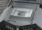
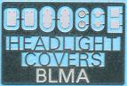
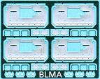
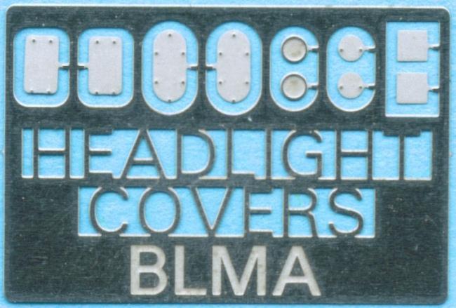
| Part #: BLMA-72 - Removed
Headlight Covers - (5 pair) |
| This etched metal set includes five different styles of covers! The first two styles on the left are for main headlights (dual lights) while the other three styles are for classification lights. This set should have you covered (pun intended) for all of your headlight covering needs. |
Model Image
|
Prototype Image
|
|
.Click
Here For
Pricing |
Click to place a
Secure Order On-Line |
| Part #: BLMA-73 - Beacon Stands
- 4 ea |
| We have designed these to be both prototypical in size and easy to install. Each set of four beacons includes one with a center hole for the easy addition of a beacon (not supplied). These etched metal beacon stands require minor bending. |
Model Image
|
Prototype Image
|
|
.Click
Here For
Pricing |
Click to place a
Secure Order On-Line |
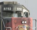
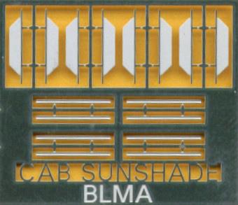
| Part #: BLMA-74 - Angled Cab
Sunshades - 8 ea |
| Nearly all locomotives have cab sunshades installed for added crew comfort. Although many different styles have been used, this "angled" style is by far the most popular and used on a wide range of motive power from the transition era to present day. |
Installation Instructions
1. Drill the mounting holes with a #80 drill bit. (Note: We have provided you with a drill jig toward the side of the etching.)
2. Once your holes are drilled, insert the Sunshade so that the half-etched portion is up. (Note: we half-etched the shade so paint will adhere nicely).
3. Once that is in place, mount the track (long, thin piece) directly under the Sunshade and secure in place with glue. |
Model Image
|
Prototype Image
|
|
.Click
Here For
Pricing |
Click to place a
Secure Order On-Line |
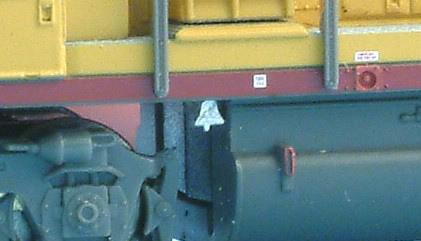
| Part #: BLMA-75 - Diesel Bells - (6) |
| All diesel locomotives are required to have bells by the FRA. For years, EMD and GE have mounted these bells on the sills/frames of locomotives. Our scale, etched-metal bells work great to simulate this ultra-common feature of diesel locomotives. |

Model Image
|

Prototype Image
|
|
.Click
Here For
Pricing |
Click to place a
Secure Order On-Line |
| Part #: BLMA- 76 - 15" Straight
Grab Irons - 20 ea |
| These highly accurate grab irons are bent into shape by machine to ensure accuracy and sharp bends. The wire is brass with a diameter of roughly .009" which makes it very easy to work with. |
Installation Instructions
1. Remove molded - on grab irons with a sharp hobby knife blade (#11) or the broader chisel blade.
2. Before sanding the shell surface smooth (if it already isn't), use the molded on grab iron markings as the template to drill your new holes or use our etched-metal drill template (BLMA #57). Drill the holes for the grab irons using a #80 or smaller drill bit.
3. Once your holes are drilled, you can sand down the surface of the shell to totally remove the old molded on grab irons (though sometimes you can get things flush with just your blade).
4. We suggest using toothless pliers to grasp the grab iron while installing.
5. By this point, all of your holes should be drilled. Without using glue, insert grab irons into the holes. This step will give you a good indication of how things are lining up before they are glued in place.
6. After the grab irons are installed without glue and look straight and uniform, remove the grab irons one by one with toothless pliers, dab the ends in super glue, then reinsert them leaving the grab iron away (not flush) with the shell. Once you have one grab iron glued in place, use it as a guide to how far out you will place the rest of the grab irons - .023" is perfect.
7. Once all of the grab irons are in place you might notice that a few are not exactly parallel. This can be fixed with a gentle hand and toothless pliers. Without grasping the wire to hard, gently bend the iron into the correct position
8. If you would like to paint the grab irons be sure you to use thin paint. |
 Installed model image
|
|
.Click
Here For
Pricing |
Click to place a
Secure Order On-Line |
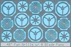
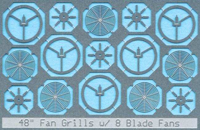
| Part
#: BLMA-81 - 48" Fan
Grill - w/o Center Plate - 8 Blades 5 ea |
| - SD40/GP40: This series of locomotives all use 48" fans for both radiator and dynamic brake cooling. For these models, you will ned BLMA #81-84 - GP30/35 & SD35: These locomotives use a combination of 36" & 48" fan grills. Our 36" Fans are BLMA #87-88 and our 48" Fans are BLMA #81-86. |
Installation Instructions
1. Drill out existing fans, leaving only the round fan housing in place (notice we do not include a new fan housing, ONLY the top grill).
2. File or sand the top of the fan housing down no more then .005” to compensate for the new fan grills’ thickness
3. Putting the shell to the side, remove all pieces from the etched metal frame using a sharp hobby knife. The large round “peace sign” looking part is the first you will work with.
4. In the middle of this part you will notice a small tab with a half etched line going through the bottom of it. Bend this tab straight up and down so it is perpendicular to the rest of the etching.
5. Next, mount your fan blade etching directly on top of the tab that you bent up in step four. The fan blade etching should be suspended above the lower piece (peace sign looking part). Secure with a dab of super glue. For added realism, turn each fan blade a few degrees (like on a ceiling fan).
6. Next, spread glue on the underside of one fan housing (meaning that you will spread glue around the opening of the fan on the INSIDE of the shell). While looking down on the model, bring your blade/bottom piece assembly up from inside the shell so the bottom piece comes in contact with the glue (spread earlier in this step). At this point, make sure that the middle of your fan blade etching is in the middle of the fan housing (it is easy to be off by a bit and this is the last chance to slightly move the assembly).
7. Once all of the fan blade assemblies are in place you can mount the top fan grill. We suggest spreading a thin layer of CA around the top of the fan housing and then placing the fan grill on top with tweezers.
8. You can either paint the top fan grills the same color as the top of the locomotive hood or leave them natural. |
Model Image
|
Installed Image
|
|
.Click
Here For
Pricing |
Click to place a
Secure Order On-Line |
Part
#: BLMA-82 48" Fan
Grill - w/o Center Plate - 10 Blades 5 ea
*Refer to BLMA 81 above for reference. |
.Click
Here For
Pricing |
Click to place a
Secure Order On-Line |
Part
#: BLMA-83 48" Fan Grill - w/Center Plate - 8 Blade 5 ea
*Refer to BLMA 81 above for reference. |
.Click
Here For
Pricing |
Click to place a
Secure Order On-Line |
Part
#: BLMA-84 - 48" Fan
Grill - w/Center Plate - 10 Blade 5 ea
*Refer to BLMA 81 above for reference. |
.Click
Here For
Pricing |
Click to place a
Secure Order On-Line |
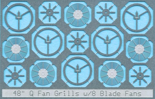
Part
#: BLMA-85 - 48" 'Q' Fan Grill - 8 Blade 5 ea
*Refer to BLMA 81 above for reference.
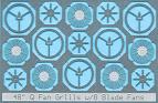 Model Image Model Image |
.Click
Here For
Pricing |
Click to place a
Secure Order On-Line |
Part
#: BLMA-86 - 48" 'Q'
Fan Grill - 10 Blade 5 ea
*Refer to BLMA 81 above for reference. |
.Click
Here For
Pricing |
Click to place a
Secure Order On-Line |
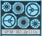
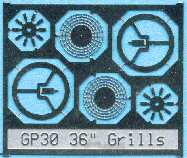
| Part
#: BLMA-87 - 36" Fan
Grill - w/Center Plate - (GP30 & more) 2
ea |
| GP30/35 & SD35: These locomotives use a combination of 36" & 48" fan grills. Our 36" Fans are BLMA #87-88 and our 48" Fans are BLMA #81-86. |
Installation Instructions
1. Drill out existing fans, leaving only the round fan housing in place (notice we do not include a new fan housing, ONLY the top grill).
2. File or sand the top of the fan housing down no more then .005” to compensate for the new fan grills’ thickness
3. Putting the shell to the side, remove all pieces from the etched metal frame using a sharp hobby knife. The large round “peace sign” looking part is the first you will work with.
4. In the middle of this part you will notice a small tab with a half etched line going through the bottom of it. Bend this tab straight up and down so it is perpendicular to the rest of the etching.
5. Next, mount your fan blade etching directly on top of the tab that you bent up in step four. The fan blade etching should be suspended above the lower piece (peace sign looking part). Secure with a dab of super glue. For added realism, turn each fan blade a few degrees (like on a ceiling fan).
6. Next, spread glue on the underside of one fan housing (meaning that you will spread glue around the opening of the fan on the INSIDE of the shell). While looking down on the model, bring your blade/bottom piece assembly up from inside the shell so the bottom piece comes in contact with the glue (spread earlier in this step). At this point, make sure that the middle of your fan blade etching is in the middle of the fan housing (it is easy to be off by a bit and this is the last chance to slightly move the assembly).
7. Once all of the fan blade assemblies are in place you can mount the top fan grill. We suggest spreading a thin layer of CA around the top of the fan housing and then placing the fan grill on top with tweezers.
8. You can either paint the top fan grills the same color as the top of the locomotive hood or leave them natural. |
Model Image
|
|
.Click
Here For
Pricing |
Click to place a
Secure Order On-Line |
Part
#: BLMA-88 36" Fan
Grill - No Center Plate - (GP35 & more) 2
ea
*Refer to BLMA 87 above for reference |
.Click
Here For
Pricing |
Click to place a
Secure Order On-Line |
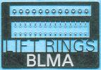
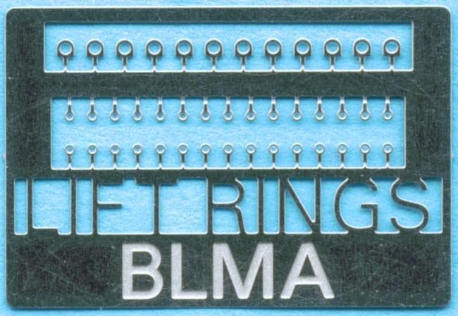
| Part
#: BLMA-90 Lift Rings - (GE & EMD) -
42 ea |
| These fine scale photo-etched lift rings are the perfect addition to your highly detailed models. Included are enough EMD and GE styles to complete at least three locomotives of either make. |
Installation Instructions
1. Remove lift rings from their etched frame with a sharp hobby knife. 2. Drill a #80 (or smaller) hole where you wish to mount the lift ring(s).
3. While grasping the "ring" portion of the part, dip the mounting end in glue and insert into model. |
Model Image
|
Prototype Image
|
|
.Click
Here For
Pricing |
Click to place a
Secure Order On-Line |
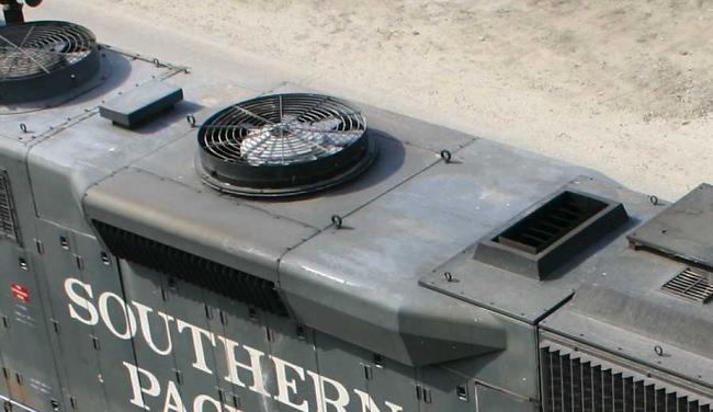
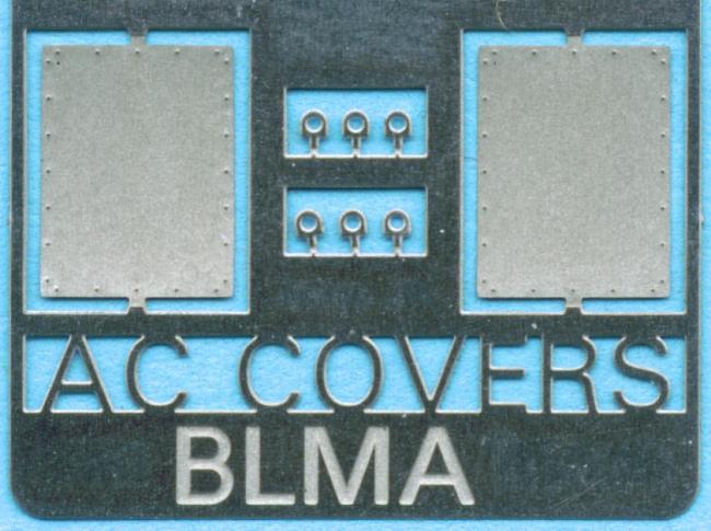
| Part #: BLMA 91 - Removed AC Cover Plate - 2 each |
| Many railroads removed the air conditioners on their locomotives and covered the area with a large, rectangular patch with rivets around the outside edge. Our Removed AC Cover Plates faithfully recreate this interesting "patch" job. |
Installation Instructions
Simply locate the area you wish to cover and secure the cover with glue. Paint as desired. |
Model Image
|

Prototype Image
|
|
.Click
Here For
Pricing |
Click to place a
Secure Order On-Line |
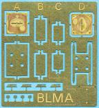
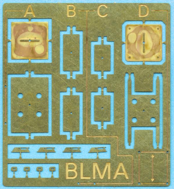
| Part #: BLMA 92 - Locomotive Antenna Stands - 4 styles |
| This set features four extremely common antenna stands. Each set of antennas has the proper Sinclair antenna style (four in the regular length and four of the shorter length). A drilling template is included for easy drilling and mounting of all of the antenna stands. . |
Installation Instructions
1. Remove the antennas from the etched frame using a sharp hobby knife.
2. Locate the style of antenna(s) you will use on your project and notice that a drilling template is provided for each style. Consult a reference photo(s) for proper placement of the antenna(s).
3. Tape the drilling template in place and drill the holes using a #80 drill bit.
4. Fold the legs of the antenna perpendicular to the center and mount into the holes drilled in step three.
5. For antenna stands A & D, it is necessary to glue the large flat plate onto the stand once the stand is mounted. Use the center hole to on both the stand and large flat piece to center everything.
6. Mount either the regular length Sinclair antenna or the short length antenna through the hole in the center of the stand.
7. Paint the stand as appropriate. We recommend painting the Sinclair antenna silver for a better effect. |
Model Image
|
Prototype Image
|
|
.Click
Here For
Pricing |
Click to place a
Secure Order On-Line |
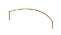
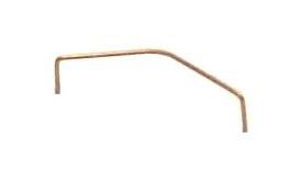
| Part #: BLMA 93 - Rear Fan Grab Iron- Round Style |
| Round Rear Fan Grab Irons are found on nearly all EMD locomotives from the SD35-45 and GP30-40-2. |
Installation Instructions
1. Remove the molded - on rear fan grab iron on your locomotive shell with a sharp hobby knife.
2. Use the markings from the removed grab and place the BLMA part on the shell to locate exactly where you need to drill your two holes (using a #80 drill bit).
3. Once your holes are drilled, sand down the surface to totally remove the old, molded - on grab iron if need be (though sometimes you can get things flush with just your blade). We suggest using toothless pliers to grasp the grab iron while installing.
4. Put the grab iron in place prior to gluing which will give you a good indication of how things are lining up before it is permanently in place.
5. After the grab is lined up, remove it with your toothless pliers then dab the ends in a small amount of glue and reinsert, leaving the grab iron away from (not flush with) the shell.
6. Adjust quickly as the glue sets fast. We also suggest adding extra dabs of glue to the inside of the shell where the ends of the grab iron will poke through. |
Model Image
|

Prototype Image
|
|
.Click
Here For
Pricing |
Click to place a
Secure Order On-Line |
| Part #: BLMA 94 - Rear Fan Grab Iron- "V" Style |
| 'V' style Rear Fan Grab Irons are found on EMD SD50-75's & EMD GP50-60's. |
Installation Instructions
*Refer to BLMA 93 above for reference |
Model Image
|
Prototype Image
|
|
.Click
Here For
Pricing |
Click to place a
Secure Order On-Line |
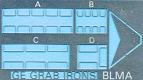
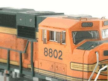
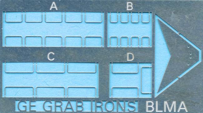
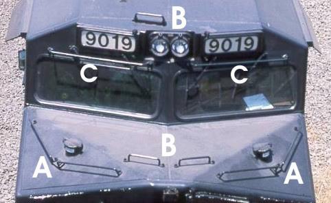
| Part #: BLMA 95 - Modern Wide Cab GE Grab Irons - fits 2 locos |
| Detailing modern GE locomotives has never been this easy! Over the past few years, many manufacturers in N-Scale have offered modern GE locomotives that have their most recent wide cab design. Up until now, the only way to get the correct grab irons for the cab and nose area was to bend them by hand. We know bending grab irons by hand is a tedious task, so we created a set of grab irons that will drop in place with the handy work of a #80 drill bit (not included) and the drilling template (included). |
Installation Instructions
Mounting with the drill template:
1. Simply tape the drill template in place on the top of the nose and drill through the holes using a #80 drill bit.
2. Remove the tape and template and mount two 'B' grab irons in place. Secure with a dab of glue from inside the shell.
Mounting without the drill template:
1. Remove the molded - on rear fan grab iron on your locomotive shell with a sharp hobby knife.
2. Use the markings from the removed grab and place the BLMA part on the shell to locate exactly where you need to drill your two holes (using a #80 drill bit).
3
. Once your holes are drilled, sand down the surface to totally remove the old, molded - on grab iron if need be (though sometimes you can get things flush with just your blade). We suggest using toothless pliers to grasp the grab iron while installing.
4. Put the grab iron in place prior to gluing which will give you a good indication of how things are lining up before it is permanently in place.
5. After the grab is lined up, remove it with your toothless pliers then dab the ends in a small amount of glue and reinsert, leaving the grab iron away from (not flush with) the shell.
6. Adjust quickly as the glue sets fast. We also suggest adding extra dabs of glue to the inside of the shell where the ends of the grab iron will poke through. |
Model Image
|
Prototype Image
|
|
.Click
Here For
Pricing |
Click to place a
Secure Order On-Line |
| Part #: BLMA 96 - Windshield Wipers - 3 Styles |
| Included in this set are three common styles of windshield wipers; short, long, and connected. With these three styles, you should be able to keep the windows clean on GE, EMD, ALCO and many other styles of locomotives. |
Installation Instructions
Simply cut the parts from the etched frame with a sharp hobby knife and glue in place (NO drilling required!). |
Model Image
|
Prototype Image
|
|
.Click
Here For
Pricing |
Click to place a
Secure Order On-Line |
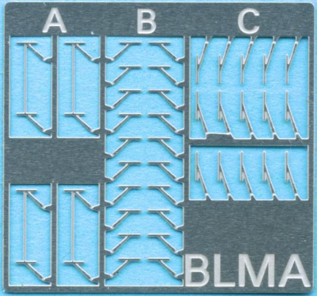
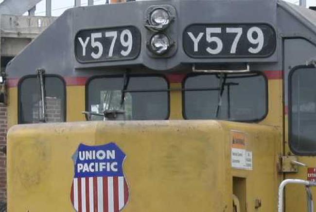
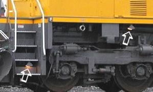
| Part #: BLMA 97 - Diesel Locomotive Step Safety Lights |
| Most diesel locomotives have these small, triangular lights installed between steps and/or under the sill directly beneath the cab for better viability at night. |
Installation Instructions
Style A: Style A can be mounted directly under the locomotive cab so that just the small light housing is visible. Simply drill a #80 hole, insert the mounting tab and secure with glue.
Style B: This style has a half-etched fold line where the light housing meets the mounting tab. Fold the light housing perpendicular to the mounting tab at the half-etched fold line. Style B is perfect for mounting under the steps leading up to the locomotives cab/walkway. Simply add glue to the tab and press in place (NO drilling required!). |
Model Image
|

Prototype Image
|
|
.Click
Here For
Pricing |
Click to place a
Secure Order On-Line |
| Part #: BLMA 98 - E/F Unit & Passenger Car Ladder Grab Irons |
We've combined the four most common styles of Ladder Grab Irons in one set to cover all of your early locomotive or passenger car detailing projects.
Features: - Four different styles provided. - Etched in .006” or .007" metal. - Drilling template provided! |
Installation Instructions
1. Remove molded - on grab irons with a sharp hobby knife blade (#11) or the broader chisel blade.
2. Before sanding the shell surface smooth (if it already isn't), use the molded on grab iron markings as the template to drill your new holes or use our etched-metal drill template (BLMA #57). Drill the holes for the grab irons using a #80 or smaller drill bit.
3. Once your holes are drilled, you can sand down the surface of the shell to totally remove the old molded on grab irons (though sometimes you can get things flush with just your blade).
4. We suggest using toothless pliers to grasp the grab iron while installing.
5. By this point, all of your holes should be drilled. Without using glue, insert grab irons into the holes. This step will give you a good indication of how things are lining up before they are glued in place.
6. After the grab irons are installed without glue and look straight and uniform, remove the grab irons one by one with toothless pliers, dab the ends in super glue, then reinsert them leaving the grab iron away (not flush) with the shell. Once you have one grab iron glued in place, use it as a guide to how far out you will place the rest of the grab irons - .023" is perfect.
7. Once all of the grab irons are in place you might notice that a few are not exactly parallel. This can be fixed with a gentle hand and toothless pliers. Without grasping the wire to hard, gently bend the iron into the correct position 8. If you would like to paint the grab irons be sure you to use thin paint. |
Model Image
|
Prototype Image
|
|
.Click
Here For
Pricing |
Click to place a
Secure Order On-Line |
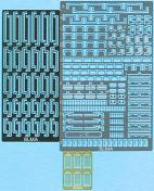
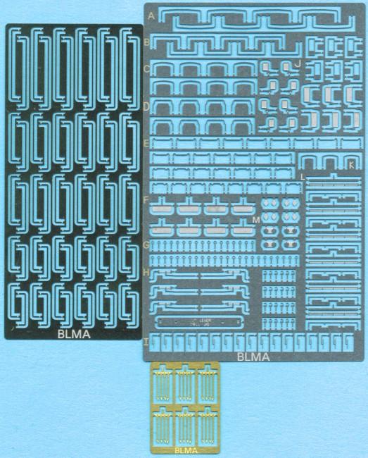
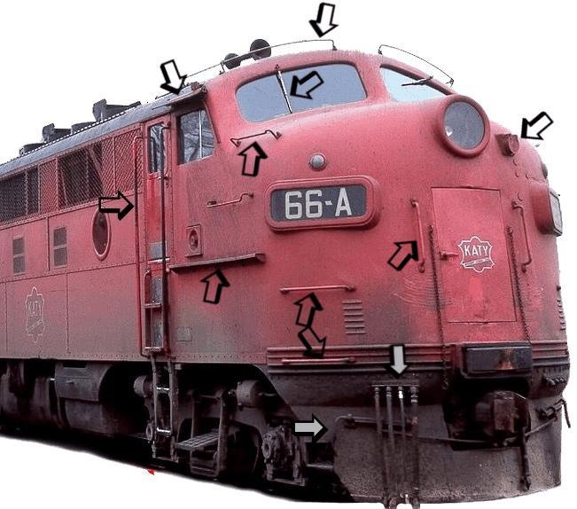
| Part #: BLMA 99 - E/F Unit Ultimate Detail Set |
We reviewed an endless assortment of E and F unit locomotive photos to make sure this set had all of the essential details needed to fully replicate up to three locomotives. Realizing there were different styles of many common components, this set includes multiple styles of generic parts, giving you, the modeler, many options to create a prototypically correct model.
Features: - Etched in .005" stainless steel for maximum detail & durability. - Extremely accurate dimensions. - Numerous details not yet available in other N-Scale detail sets. - Completes three models.
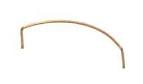
Parts Include: - Cab Sunshades - Rear View Mirrors (three styles) - Cut Levers - Ladder Grab Irons (four styles) - Windshield Wipers - Curved Grab Irons Above Windshield - MU Hoses - MU Cable Receptacle Covers - Tall Grab Irons - Cab Side Mounted Walkway - Numerous Custom Curved Grab Irons |
Installation Instructions
Like most of our products, many of the parts in this massive set of details mount into a #80 hole. |
Model Image
|

Prototype Image
|
|
.Click
Here For
Pricing |
Click to place a
Secure Order On-Line |
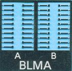
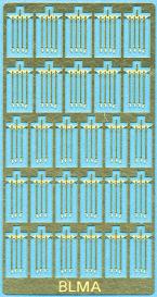
| Part #: BLMA 100 - MU Hoses |
MU Hoses are found on all diesel and electric locomotives. The "MU" in the name refers to the fact that these hoses allow for Multiple Unit lash-ups where two or more locomotives are used in a single consist.
Our etched metal MU Hoses capture the "thin" look of the real thing while also taking advantage of the metals durability (over that of cast metal or other fine materials) |
Installation Instructions
Simply drill a single #80 hole, put the mounting tab on the top of the air hoses into the hole, secure with glue and enjoy! We recommend painting the hoses black with a small touch of silver on the hose connectors (at the end of each hose). |
Model Image
|
Prototype Image
|
|
.Click
Here For
Pricing |
Click to place a
Secure Order On-Line |
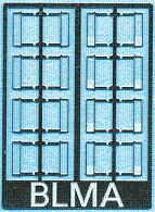
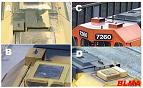
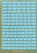
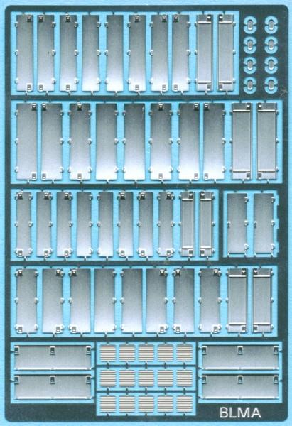
| Part #: BLMA 101 - Diesel Locomotive Hood Doors |
Featuring FOUR different standard size diesel locomotive hood doors in many different hinge/latch configurations, this set will definitely come in handy for your next kit bashing project.
Locomotive Parts Included: - Four Hood Doors in numerous hinge/latch configurations as well as reversed doors with inside face detail present. - Two EMD style generator access doors. - Standard EMD Cab Sub-base Equipment Doors. - EMD Sight Glasses. - Numerous standard louvers for early locomotives. |
Model Image
|
Prototype Image
|
|
.Click
Here For
Pricing |
Click to place a
Secure Order On-Line |
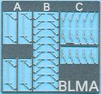
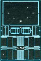
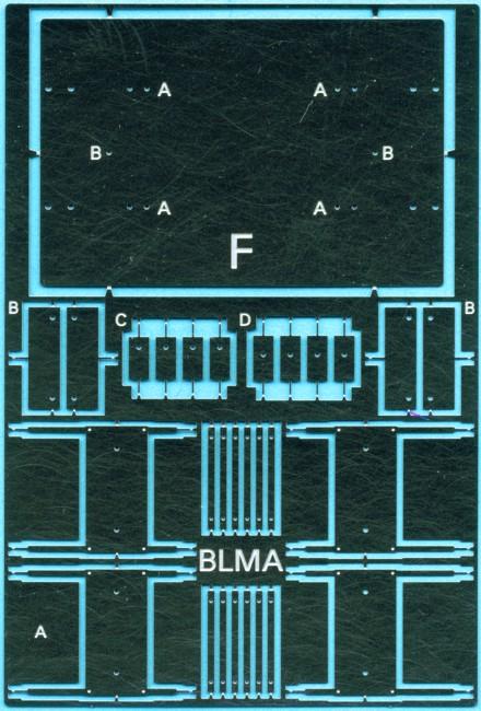
| Part #: BLMA 102 - Remote Controlled Locomotive (RCL) Antenna Stands |
| Disliked by many railroaders, Remote Controlled Locomotives (RCL’s) are becoming a common site around the country. Our new set of numerous RCL Antenna Stands will make your modern switching fleet stand out! This detail set is etched in .006" brass for scale fidelity, durability, and it premium paint surface. Included in this set are four of the most common remote controlled locomotive antenna stand styles. This product also features a drill template for styles A and B. |
Installation Instructions
- Product Key:
A. Large Flat Top Stand: This stand is mounted on the angled portion of the locomotives cab roof. Note that the antenna stand top may be mounted at the roof height or just above the roof height; our drilling jig is equipped for both styles.
B. Narrow, Long Stand: Used on many odd-ball switchers such as SW1500’s, SD9’s, and more, this narrow stand mounts where the cab roof angles down on either side of the cab.
C. Square Stand (two sides): Mounted in the same location as stand B, this small stand has only one side and top. Like antenna stand B, this product mounts flush with the roof line.
D. Square Stand (three sides): Mounted like C, this stand extends above the roof line and utilizes three sides. The antenna foundations for styles A and B are located in the bottom center of the fret (between the A’s). Locate prototype photos for exact placement of these stands.
Instructions:
• Bend the sides of the provided drill template so they match the angle of your cabs roof line. The large ‘F’ on the template indicates the front.
• The drill template works for antenna styles A & B only. Note that style A has two sets of holes near the edge of both sides. If you are mounting the style A at the roof line height, remove the inside (short) legs and only drill the two outermost holes; drill the top holes (located next to the A’s) and the second to the outermost holes for a stand that sits above the roof line.
• Drill holes using a #80 drill (enlarge hole if necessary) and secure the stands with CA glue.
|
Model Image
|
Prototype Image
|
|
.Click
Here For
Pricing |
Click to place a
Secure Order On-Line |
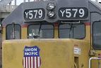
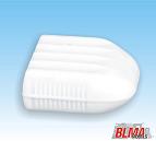
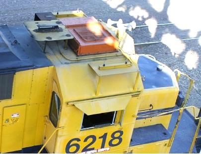
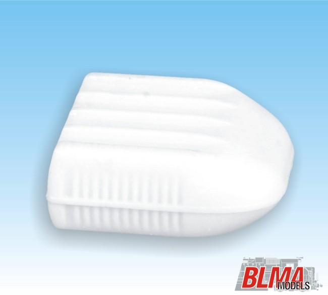
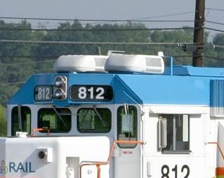
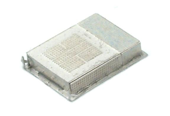
| Part
#: BLMA 103 - Modern RV Style Locomotive Air Conditioner - 4 per pack |
| Found on an increasing number of rebuilt and new locomotives, these RV style air conditioners are a common site on modern locomotives. Upgrade your modern fleet with these extremely accurate models. These RV Style Air Conditioners can be found on railroads such as Union Pacific, BNSF, Canadian National, Illinois Central, Florida Tri-Rail, and more! This product will be molded in white plastic; mounting will consist of only gluing the air conditioner to the roof of the locomotive cab. |
Model Image
|
Prototype Image
|
|
.Click
Here For
Pricing |
Click to place a
Secure Order On-Line |
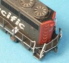
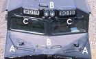
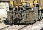
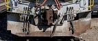
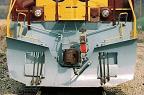
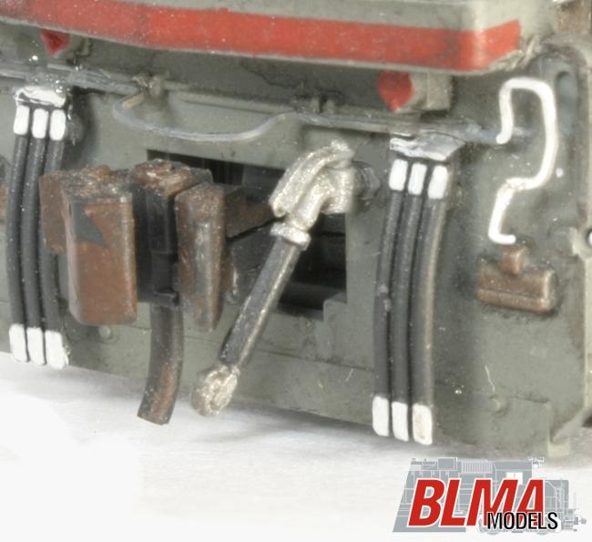
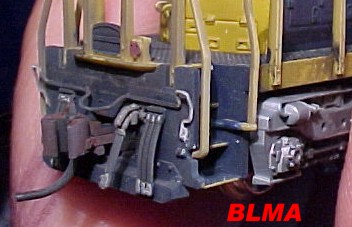
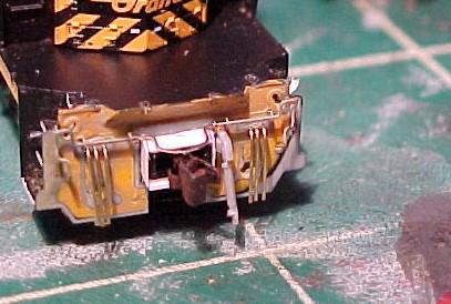
| Part
#: BLMA 105 - EMD Pilot Face Layovers |
A majority of EMD's mid-series locomotives (GP30-60 & SD40-70+) use a very standard looking pilot. Because these pilots feature numerous details that require drilling, we've designed a simple layover for EMD pilots that will drastically cut down your modeling time and serve as a drill template for our Cut Levers & MU Hoses.
NOTES: - There are an extreme number of pilot variations (including rivet and kick plate detail); this set was designed to incorporate some of the most common designs. |
Installation Instructions
1. Remove etched metal parts from their frame using a sharp hobby knife (be careful!).
2. Remove the couplers from the locomotive.
3. Cut, file, and/or sand off the molded-on pilot detail on your GP or SD pilot. It is imperative that the front pilot be completely flat.
4. Test fit the etched pilot layover. We have designed this product to work with most EMD models, but it might be necessary to file away portions of the top if the handrails foul the etching.
5. Using a small amount of CA (glue) spread evenly across the pilot, lay the etching in place.
6. Use a #80 drill (or smaller) to drill out all of the pilot holes (these holes are for the Cut Lever, MU Hoses, and MU Hose Holders. It is necessary to use a slightly larger drill for the mounting of our #69 Trainline Air Hose.
7. Once all of the holes are drilled, insert the additional products (links below) to easily finish the pilot of your model.
8. Repeat steps 1-7 for both ends of your model and paint as desired.
|
Model Image
|
Prototype Image
|
|
.Click
Here For
Pricing |
Click to place a
Secure Order On-Line |
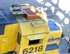
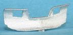
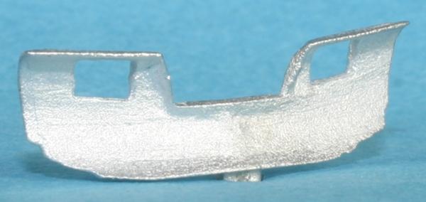
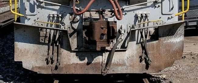
| Part
#: BLMA 201 - Snow Plow - Small Style #1 - 2 per pack |
| We are pleased to offer extremely accurate, ultra-common snow plows cast in durable metal. These all new snow plows feature exact scale dimensions (we literally measured the prototypes!) and a paint-friendly surface. |
Installation Instructions
Simply mount in place with CA, paint as desired and enjoy! |
Model Image
|
Prototype Image
|
|
.Click
Here For
Pricing |
Click to place a
Secure Order On-Line |
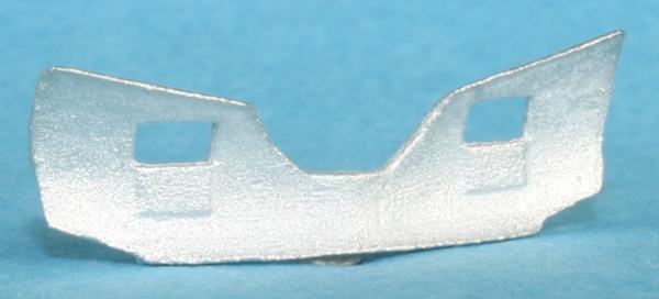
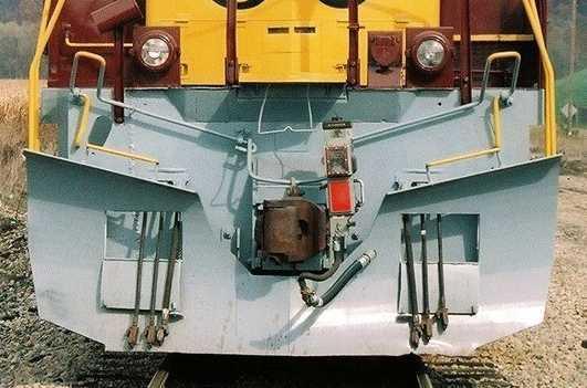
| Part
#: BLMA 210 - Snow Plow - Large Style #1 - 2 per pack |
| We are pleased to offer extremely accurate, ultra-common snow plows cast in durable metal. These all new snow plows feature exact scale dimensions (we literally measured the prototypes!) and a paint-friendly surface. |
Installation Instructions
Simply mount in place with CA, paint as desired and enjoy! |

Model Image
|
Prototype Image
|
|
.Click
Here For
Pricing |
Click to place a
Secure Order On-Line |
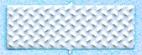
| Part
#: BLMA 250 - Diamond Tread Plate - Various Shapes & Strips |
Diamond Tread Plate is found on locomotives, freight cars, industrial buildings, stairways and more!
Our new Diamond Tread Plate features extremely fine-scale tread in numerous shapes and sizes.
This product is perfect for that special project of yours. This product is etched in .006" brass, making it very easy to cut and glue. |
Installation Instructions
Simply cut to the desired size using regular scissors and glue in place with CA. |
|
|
|
.Click
Here For
Pricing |
Click to place a
Secure Order On-Line |
|
*NEW* Ultra-Common Air Horns
|
| Part #: BLMA-221 Air Horns - Leslie S3L (2 per pack) |
These all-new horns feature exact scale dimensions, a paint-friendly surface, and easy mounting.
Two lost-wax brass castings per pack. |
|
|
|
.Click
Here For
Pricing |
Click to place a
Secure Order On-Line |
| Part #: BLMA-222 Air Horns - Leslie S3L-R (2 per pack) |
These all-new horns feature exact scale dimensions, a paint-friendly surface, and easy mounting.
Two lost-wax brass castings per pack. |
|
|
|
.Click
Here For
Pricing |
Click to place a
Secure Order On-Line |
| Part #: BLMA-223 Air Horns - Nathan M3R1 (2 per pack) |
These all-new horns feature exact scale dimensions, a paint-friendly surface, and easy mounting.
Two lost-wax brass castings per pack. |
|
|
|
.Click
Here For
Pricing |
Click to place a
Secure Order On-Line |
| Part #: BLMA-224 Air Horns - Nathan K5HR24 (2 per pack) |
These all-new horns feature exact scale dimensions, a paint-friendly surface, and easy mounting.
Two lost-wax brass castings per pack. |
|
|
|
.Click
Here For
Pricing |
Click to place a
Secure Order On-Line |
| Part #: BLMA-225 Air Horns - Leslie S5T-R (2 per pack) |
These all-new horns feature exact scale dimensions, a paint-friendly surface, and easy mounting.
Two lost-wax brass castings per pack. |
|
|
|
.Click
Here For
Pricing |
Click to place a
Secure Order On-Line |
| Part #: BLMA-226 Air Horns - Leslie S5T (2 per pack) |
These all-new horns feature exact scale dimensions, a paint-friendly surface, and easy mounting.
Two lost-wax brass castings per pack. |
|
|
|
.Click
Here For
Pricing |
Click to place a
Secure Order On-Line |
| Item Description |
Pricing
| Order link |
Stock Checks:
Inventory is a fluid commodity. It changes by the
hour (sometimes by the minute). To retain our pricing structure
we maintain stock levels designed to turnover 6 times each
year. We cannot guarantee stock status till we have an order
in hand. All product is subject to prior sale. If we confirm
that we have it, and, while we are waiting for the order
it sells, you would be upset that we did not hold it.
We used to hold items but learned a VERY EXPENSIVE lesson.
When we held items for customers’ orders, the order
never materialized 80%+ of the time. We lost out on
the orders placed while the item was on hold. Also
we wasted staff time that could have been used to pull actual
orders.
Since we are well known for finding older stock the fact
that it may not be on our shelves at this minute does not
mean we can’t get it. So, as we spell out on our terms
pages, we don’t do it anymore. You may, however, call in and we will tell you if the items
are available and if possible attempt to locate what we
don’t have while you are on the phone. |
| Last Update by: GJC |
| Saturday, July 6, 2013 5:38 PM |
|
 Wig-Wag, LLC


